Forming node sequences
A connection between two nodes represents that the output of the first node becomes the input to the second node. Connections between nodes are one way, from one node to another. Direction is indicated by a small arrow at the end of the line representing the connection on the flowchart. You choose the direction when creating the connection.
Here is an example of a node sequence:
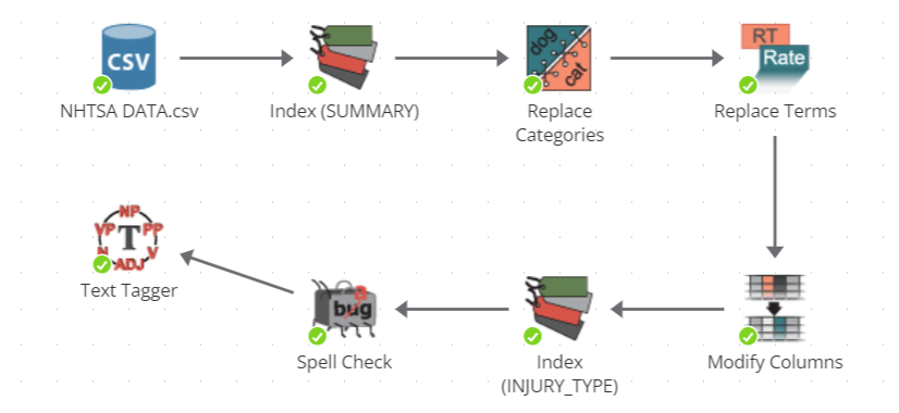
How data moves along a node sequence
Data essentially moves along a conveyor belt of nodes, with each worker node doing something to the data as it moves along.
However, saying that data moves along the sequence is slightly inaccurate. The data is not removed from an earlier node when passed along to the next node in a sequence. Rather, the results of each successive node in the sequence represent the cumulative changes to the data up to the node’s position within the sequence.
Node output is immutable
Node output is immutable, meaning that once output is created, it cannot be modified. In other words, a node cannot modify its input because that input is the output of some other node, and every node’s output is immutable.
To illustrate this concept, consider a simple sequence such as a CSV Source node connected to a Filter Columns node. It is tempting to describe the Filter columns as modifying the dataset produced by the CSV Source node. This is an intuitive interpretation given the name of the node and how it is represented on the flowchart in a sequence. However, what actually happens is that the Filter Columns node outputs a new dataset that is a partial copy of its input dataset. The original dataset produced by the CSV Source node is not modified. The columns removed by the Filter Columns node are still present in the output of the earlier data source node. It is just that those columns are not present in the output of the Filter Columns node.
Immutability provides several benefits, namely that it is easy to assess the correctness of the output of any node in a sequence knowing that its output directly corresponds to only its current configuration and current input. Whenever you encounter unexpected results for a node, review the outputs of nodes earlier in the sequence to find the earliest point of departure from expectation.
Referring to nodes in a sequence
This user manual uses several terms to refer to specific nodes within a given sequence. For example, in a sequence of just two nodes, such as a connection from some node A to some node B, the documentation uses certain terms to specifically refer to A or B. Specifically:
-
'A' may be referred to as the source node, the parent node, the root node, the root, the preceding node, the prior node, the prior, the predecessor node, the predecessor, a node which is upstream, a producer, a sender, an ancestor, an ancestral node, or simply a node which is earlier in the sequence.
-
'B' may be referred to as the target node, receiving node, dependent node, descendant node, destination node, consuming node, child node, successive node, or downstream node.
In a sequence of more than two nodes, the very first node in the sequence may be referred to as the parent, root, or source node. The very last node may be referred to as the final or terminal node.
Design first, execute second
You do not have to immediately execute a node upon adding and configuring the node. You can work with the output of a node before the node has executed. This characteristic of using PolyAnalyst is particularly important when working with larger datasets. PolyAnalyst is designed to support the ability to create a lengthy sequence of nodes quickly and easily during the day, and then execute all of the steps of the sequence over night. You do not have to add a node, then immediately configure the node, execute the node, wait while it executes, and then add another node. Instead, you can add a node, configure the node, and then add another node, and so forth, and then, once all of your nodes are added and configured, execute them all at once.
Performing tangential analyses
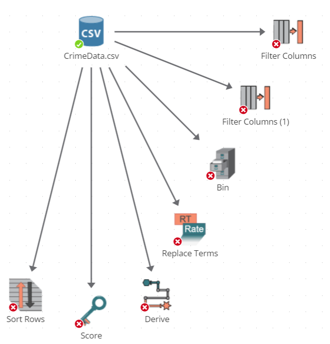
A node can be connected to multiple nodes. More than one node can consume the output of a node. In other words, you can make a sequence split into two or more subsequences. For example, the following image shows how the output of the Crime Data CSV Source node is repeatedly used as input to a variety of other nodes.
Here is another example of pursuing tangential analyses:
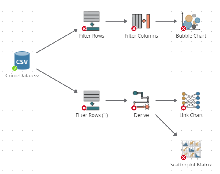
In this example, the two Filter Rows nodes each extract a subset of records from the dataset produced by the CSV Source node. From this point of divergence onward, two separate analyses are performed. Each analysis works with its own limited view of the original data according to how each of the filter nodes was configured.
Restrictions on node connections
Not all nodes may be connected to one another. You can only create a connection between two nodes if the output of the parent node is an acceptable type of input for the child node.
Each node in this documentation describes its allowable inputs and the type of output it produces.
Some nodes accept (and require) more than one input.
Some nodes require multiple types of input.
If a node already has a connection from another node, and you want to replace that connection with one from another node, you will need to remove the old connection and then create a new one from the other node.
Creating a connection between two nodes
Let’s walk through the process of creating a connection. If you have not already done so, add a new Filter Columns node to the flowchart. The Filter Columns node is located in the Column operations section of the node palette. You will want to use the same steps for adding the node as you did for the CSV Source node in a previous example.
We are now going to connect the CSV Source node to the Filter Columns node.
-
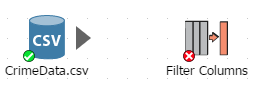
Left click down on the line handle located next to the CSV Source node from which the connection should start. The line handle is a tiny arrow located to the right of the icon, and it is circled in the following image. If you do not see the handle, hover the mouse over the node’s icon on the flowchart.
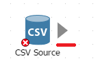
-
Not all nodes provide line handles. The absence of a line handle means that a connection cannot be started from the node. In addition, the line handle will only appear next to the icon on the flowchart when there is both a node to connect from and a node to be connected. For example, the following image displays a line handle next to the node named CrimeData because there is a candidate node to which CrimeData can be connected (i.e., a node called Filter Columns).
-
Create a connection. Click down on the handle of the CSV Source node with the left mouse button, and while holding the button down, move the mouse cursor so that it is hovering over the Filter Columns node. As you move you will notice a line being drawn from the handle to the cursor (see the screenshot below).
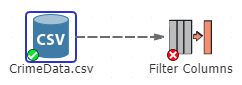
-
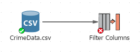
When your mouse cursor is on top of the Filter Columns node icon, release the mouse. PolyAnalyst creates the connection. If you missed, PolyAnalyst cancels the operation. Otherwise, you should now see the following:
Other ways of connecting nodes
There is another way to connect nodes on the flowchart. You can right-click the selected node and select Add node… from the menu. In the new window locate the node you want to connect it with. Use the filter window if necessary. The new node will be added to the flowchart and connected with its parent.
When can connections be created?
You can connect nodes together before configuring or executing them. You do not have to configure a node before creating a connection from the node to another node.
Disconnecting nodes
To remove a connection between two nodes, right click on the connection line between the two nodes and select Unlink.
Deleting a connection affects the state of downstream nodes. If downstream nodes were previously in a completed state, then deleting a connection may cause those downstream nodes to delete results and revert to an earlier state.
Some nodes require a connection prior to configuration
Generally, once you add a node to the flowchart, you can access the node’s properties at any time. However, certain nodes cannot be properly configured until the requisite input connections are established. In some cases, nodes will display an error message when opening a node’s properties window.
The properties window for a node may also appear differently based on whether input connections exist. For example, certain tabs may be hidden or disabled when required input is not available.
In limited cases, a node cannot be properly configured until its preceding node (or nodes) has been connected, configured, and also executed.
Configuring a node affects connected nodes
The states of nodes occurring later in a sequence depend upon the state of nodes occurring earlier in the sequence. For example, when you reconfigure a completed node in a sequence of completed nodes, its output is removed. This removal of output causes a wave of resets down the chain of subsequent nodes, causing all the outputs of nodes occurring later in a sequence to also be deleted.
Executing a node affects connected nodes
Although you generally initiate execution by choosing to execute a particular node, you are always possibly executing the entire sequence of nodes containing the node.
When choosing to execute a node that is in the middle of a sequence of connected nodes, PolyAnalyst backtracks to the start of the sequence and sequentially executes each node in the sequence.
If any earlier node fails to execute, the node chosen to execute also fails.
When backtracking and encountering a node that has completed processing, PolyAnalyst will not re-execute the earlier node. Instead, PolyAnalyst uses its current output, stops backtracking, and proceeds executing subsequent nodes.
If you wanted a different behavior, and specifically wanted that earlier nodes that already have output to re-execute, then you need to start execution from one of the earlier nodes, and not the later node.
When you execute a node, all the successive nodes that are connected are also executed. To avoid this, select the Execute to here option from the node’s right click menu.
In limited cases, when executing a node that forks a sequence into two sequences, PolyAnalyst may execute both of the subsequent sequences concurrently. By default, concurrent node execution is not enabled, and all the nodes in the second chain are merely queued for execution and do not start executing until all the nodes in the first chain complete.